
Calculation Modules
The core of ENERCALC's Structural Engineering Library is its calculation modules. Dating back to 1983 when the Structural Engineering Library was released as a set of spreadsheet templates, our modules are designed as “fill-in-the-blanks” style of interactive programs. Simply type in a value and the resulting analysis or design is instantly there for your review.
All modules in the currently available build conform to:
IBC 2018 / 2015
CBC 2019 / 2016
ASCE 7-16 / 7-10
ACI 318-14
ACI 530-13
TMS 402-16
AISC 360-16 / 360-10
NDS 2018 / 2015
The calculation module list is an ever-expanding set of structural calculations that provide analysis and design for the elements of a building. As requests are received from our users we develop additional modules…..and make use of the proven steel, concrete, timber, finite element analysis, and other engineering “solvers” we have developed.
Currently Included Modules:
Click on a module name to see a module-specific feature list
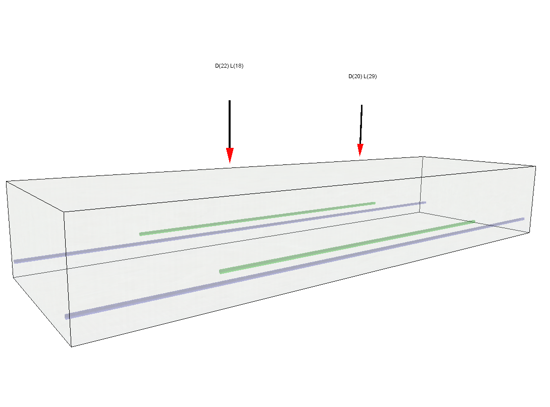
 Multiple Simple Beam
- Analyzes and designs up to 12 different non-composite beams within a single calculation item
- Permits wood, steel, and concrete beams
- Permits cantilevers to be modeled at one end or both ends
- Includes full wood and rolled steel section databases
- Allows fixed or pinned support conditions
- Incorporates point loads, concentrated moments, full-length uniform loads, partial-length uniform loads, and trapezoidal loads
- Includes option to perform automatic unbalanced live load placement (skip-loading)
- Incorporates either ASD or LRFD design methodology
- Offers the convenience of fill-in-the-blanks style forms and instantaneous recalculation to facilitate the evaluation of "what-if" scenarios
- Provides highly efficient results summaries as well as generous detail in the on-screen and printed results
- Provides sketch graphics to verify dimensions and load placement - including rich, 3D graphics that support zoom, pan, and many customizable view options. Example 3D image shown below.
- Provides shear, moment and deflection diagrams for all load cases

 Steel Beam
- Analyzes and designs individual non-composite steel beams
- Permits multi-span continuous beams
- Permits cantilevers to be modeled at one end or both ends
- Allows fixed or pinned support conditions
- Includes full rolled steel section database
- Incorporates point loads, concentrated moments, full-length uniform loads, partial-length uniform loads, and trapezoidal loads
- Includes option to perform automatic unbalanced live load placement (skip-loading)
- Incorporates either ASD or LRFD design methodology
- Considers user-specified allowable ratios for total load deflection and live load deflection
- Offers the convenience of fill-in-the-blanks style forms and instantaneous recalculation to facilitate the evaluation of "what-if" scenarios
- Provides highly efficient results summaries as well as generous detail in the on-screen and printed results
- Provides sketch graphics to verify dimensions and load placement - including rich, 3D graphics that support zoom, pan, and many customizable view options. Example 3D image shown below.
- Provides shear, moment and deflection diagrams for all load cases
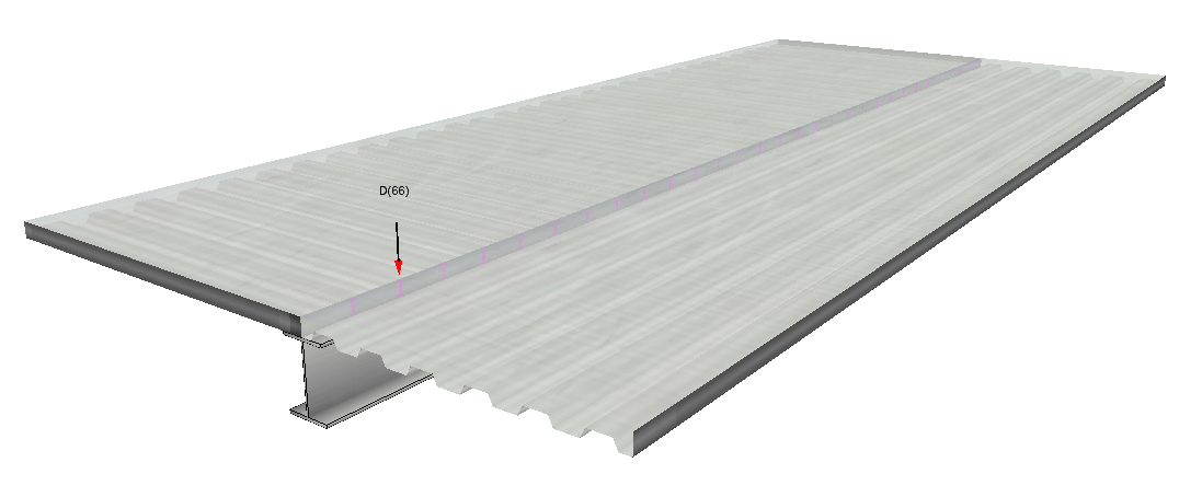
 Composite Steel Beam
- Analyzes and designs individual composite steel beams
- Includes full rolled steel section database and metal floor deck database
- Incorporates point loads, concentrated moments, full-length uniform loads, partial-length uniform loads, and trapezoidal loads
- Allows user to specify the timing of the application of individual loads with respect to the concrete achieving 75% of design strength
- Incorporates either ASD or LRFD design methodology
- Considers user-specified allowable ratios for total load deflection and live load deflection
- Offers the convenience of fill-in-the-blanks style forms and instantaneous recalculation to facilitate the evaluation of "what-if" scenarios
- Provides highly efficient results summaries as well as generous detail in the on-screen and printed results
- Provides sketch graphics to verify dimensions and load placement - including rich, 3D graphics that support zoom, pan, and many customizable view options. Example 3D image shown below.
- Provides shear, moment and deflection diagrams for all load cases
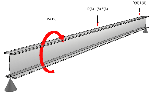
 Steel Beam with Torsional Loads
- Analyzes and designs individual non-composite steel beams
- Allows fixed or pinned support conditions
- Includes full rolled steel section database
- Incorporates point loads, full-length uniform loads, partial-length uniform loads, and trapezoidal loads at a specified eccentricity
- Incorporates concentrated moments causing bending or torsion
- Incorporates either ASD or LRFD design methodology
- Considers user-specified allowable ratios for total load deflection and live load deflection
- Offers the convenience of fill-in-the-blanks style forms and instantaneous recalculation to facilitate the evaluation of "what-if" scenario
- Provides highly efficient results summaries as well as generous detail in the on-screen and printed results
- Provides sketch graphics to verify dimensions and load placement - including rich, 3D graphics that support zoom, pan, and many customizable view options. Example 3D image shown below.
- Provides shear, moment and deflection diagrams for all load cases

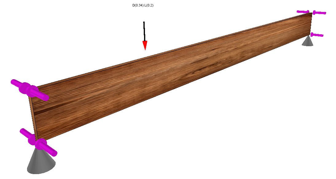
 Wood Beam
- Analyzes and designs individual sawn lumber, glulam, and manufactured wood beams
- Permits multi-span continuous beams, Permits cantilevers to be modeled at one end or both ends
- Allows fixed or pinned support conditions
- Includes sawn lumber and glulam databases, and a growing list of databases for manufactured wood products
- Incorporates point loads, concentrated moments, full-length uniform loads, partial-length uniform loads, and trapezoidal loads
- Includes option to perform automatic unbalanced live load placement (skip-loading)
- Incorporates either ASD or LRFD design methodology
- Considers user-specified allowable total and live load deflection ratios
- Provides highly efficient results summaries as well as generous detail in the on-screen and printed results
- Provides sketch graphics to verify dimensions and load placement - including rich, 3D graphics that support zoom, pan, and many customizable view options. Example 3D image shown below.
- Provides shear, moment and deflection diagrams for all load cases
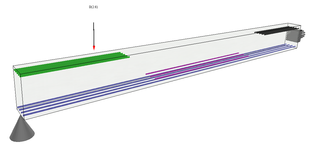
 Concrete Beam
- Analyzes and designs individual reinforced concrete beams
- Permits multi-span continuous beams
- Permits cantilevers to be modeled at one end or both ends
- Allows fixed or pinned support conditions, Permits up to six groups of reinforcing bars per span
- Capable of analyzing and designing rectangular, tee, H, and trapezoidal shaped sections
- Incorporates point loads, concentrated moments, full and partial-length uniform loads, and trapezoidal loads
- Includes option to perform automatic unbalanced live load placement (skip-loading)
- Considers user-specified allowable ratios for total load deflection and live load deflection
- Provides sketch graphics to verify dimensions and load placement - including rich, 3D graphics that support zoom, pan, and many customizable view options. Example 3D image shown below.
- Provides shear, moment and deflection diagrams for all load cases
 Masonry Beam
- Analyzes and designs individual single-span masonry lintels
- Allows fixed or pinned support conditions
- Capable of analyzing and designing rectangular reinforced sections
- Incorporates point loads and uniformly distributed loads
- Incorporates either ASD or SD design methodology
- Offers the convenience of fill-in-the-blanks style forms and instantaneous recalculation to facilitate the evaluation of "what-if" scenarios
- Provides highly efficient results summaries as well as generous detail in the on-screen and printed results
- Provides sketch graphics to verify dimensions and load placement - including rich, 3D graphics that support zoom, pan, and many customizable view options. Example 3D image shown below.
- Provides shear, moment and deflection diagrams for all load cases
 General Beam Analysis
- Provides analysis capability (without design or code checking functionality) for an individual beam of specified section properties
- Permits multi-span continuous beams
- Permits cantilevers to be modeled at one end or both ends
- Allows fixed or pinned support conditions
- Incorporates point loads, concentrated moments, full-length uniform loads, partial-length uniform loads, and trapezoidal loads
- Includes option to perform automatic unbalanced live load placement (skip-loading)
- Offers the convenience of fill-in-the-blanks style forms and instantaneous recalculation to facilitate the evaluation of "what-if" scenarios
- Provides highly efficient results summaries as well as generous detail in the on-screen and printed results
- Provides rich, 3D graphics that support zoom, pan, and many customizable view options. Example 3D image shown below.

 Steel Column
- Analyzes and designs individual steel columns
- Permits slenderness to be defined in a variety of ways, including the use of built-in non-sway alignment charts
- Allows various top and bottom support conditions
- Includes full rolled steel section database
- Considers combined axial load and biaxial bending
- Axial loads may be specified with or without eccentricity
- Lateral loads can be point loads, concentrated moments, full-length uniform loads, and partial-length uniform loads creating bending about either axis
- Incorporates either ASD or LRFD design methodology
- Offers the convenience of fill-in-the-blanks style forms and instantaneous recalculation to facilitate the evaluation of "what-if" scenarios
- Provides highly efficient results summaries as well as generous detail in the on-screen and printed results
- Provides sketch graphics to verify dimensions and load placement - including rich, 3D graphics that support zoom, pan, and many customizable view options. Example 3D image shown below.

 Wood Column
- Analyzes and designs individual wood columns
- Permits slenderness to be defined in a variety of ways
- Allows various top and bottom support conditions
- Includes full wood stress database with sawn lumber sections, glulam members and a growing number of proprietary manufactured wood products
- Considers combined axial load and biaxial bending
- Axial loads may be specified with or without eccentricity
- Lateral loads can be point loads, concentrated moments, full-length uniform loads, and partial-length uniform loads creating bending about either axis
- Incorporates either ASD or LRFD design methodology
- Offers the convenience of fill-in-the-blanks style forms and instantaneous recalculation to facilitate the evaluation of "what-if" scenarios
- Provides highly efficient results summaries as well as generous detail in the on-screen and printed results
- Provides sketch graphics to verify dimensions and load placement - including rich, 3D graphics that support zoom, pan, and many customizable view options. Example 3D image shown below.

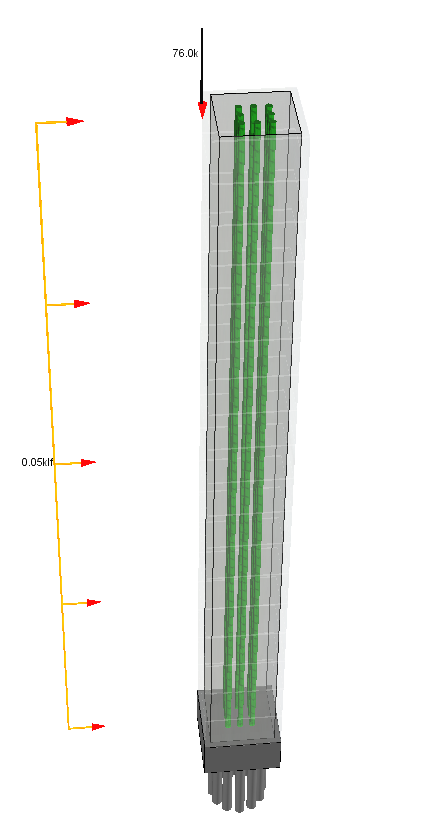
 Concrete Column
- Analyzes and designs individual concrete columns
- Permits slenderness to be defined in a variety of ways, including the use of built-in non-sway alignment charts
- Allows various top and bottom support conditions
- Includes twelve parametrically defined concrete section shapes with user-definable rebar sets
- Considers combined axial load and biaxial bending
- Axial loads may be specified with or without eccentricity
- Lateral loads can be point loads, concentrated moments, full-length uniform loads, and partial-length uniform loads creating bending about either axis
- Offers the convenience of fill-in-the-blanks style forms and instantaneous recalculation to facilitate the evaluation of "what-if" scenarios
- Provides highly efficient results summaries as well as generous detail in the on-screen and printed results
- Provides sketch graphics to verify dimensions and load placement - including rich, 3D graphics that support zoom, pan, and many customizable view options. Example 3D image shown below.

 Masonry Column
- Analyzes and designs individual masonry columns
- Permits slenderness to be defined in a variety of ways
- Allows various top and bottom support conditions
- Considers square or rectangular section shapes with user-definable rebar sets
- Considers combined axial load and uniaxial bending
- Axial loads may be specified with or without eccentricity
- Lateral loads can be point loads, concentrated moments, full-length uniform loads, and partial-length uniform loads creating bending about X-X axis
- Incorporates either Allowable Stress Design or Strength Design methodology
- Offers the convenience of fill-in-the-blanks style forms and instantaneous recalculation to facilitate the evaluation of "what-if" scenarios
- Provides highly efficient results summaries as well as generous detail in the on-screen and printed results
- Provides sketch graphics to verify dimensions and load placement - including rich, 3D graphics that support zoom, pan, and many customizable view options. Example 3D image shown below.
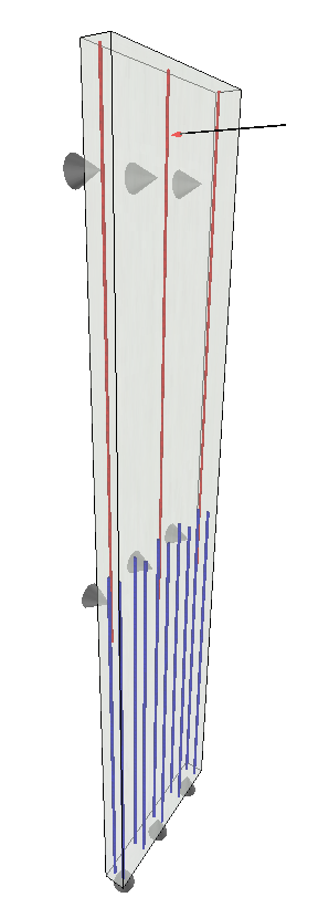
 Concrete Slender Wall
- Analyzes and designs individual concrete walls
- Analysis incorporates P-Delta deflections
- Permits 1-story or 2-story walls with or without parapet
- Allows various top and bottom support conditions
- Incorporates reveals with various reinforcing options
- Considers combined axial load and bending
- Axial loads may be specified with or without eccentricity
- Lateral loads can be concentrated loads, distributed loads, or uniform pressure loads from wind or seismic
- Offers the convenience of fill-in-the-blanks style forms and instantaneous recalculation to facilitate the evaluation of "what-if" scenarios
- Provides highly efficient results summaries as well as generous detail in the on-screen and printed results
- Includes rich, 3D graphics that support zoom, pan, and many customizable view options. Example 3D image shown below.
 Masonry Slender Wall
- Analyzes and designs individual masonry walls
- Analysis incorporates P-Delta deflections
- Permits 1-story or 2-story walls with or without parapet
- Allows various top and bottom support conditions
- Considers combined axial load and bending
- Axial loads may be specified with or without eccentricity
- Lateral loads can be concentrated loads, distributed loads, or uniform pressure loads from wind or seismic
- Offers the convenience of fill-in-the-blanks style forms and instantaneous recalculation to facilitate the evaluation of "what-if" scenarios
- Provides highly efficient results summaries as well as generous detail in the on-screen and printed results
- Includes rich, 3D graphics that support zoom, pan, and many customizable view options. Example 3D image shown below.

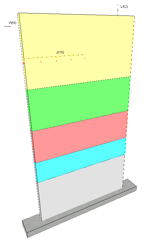
 Concrete Shear Wall
- Analyzes and designs individual concrete shear walls
- Allows solid walls and walls with setbacks
- Considers combined axial load and bending
- Vertical and lateral loads can be specified as point loads or uniformly distributed loads
- Offers the option to design a wall footing
- Offers the convenience of fill-in-the-blanks style forms and instantaneous recalculation to facilitate the evaluation of "what-if" scenarios
- Provides highly efficient results summaries as well as generous detail in the on-screen and printed results
- Includes rich, 3D graphics that support zoom, pan, and many customizable view options. Example 3D image shown below.
 Masonry Shear Wall
- Analyzes and designs individual masonry shear walls
- Allows solid walls and walls with setbacks
- Considers combined axial load and bending
- Considers the resistance from bond beam reinforcing and/or horizontal joint reinforcing
- Vertical and lateral loads can be specified as point loads or uniformly distributed loads
- Offers the option to design a wall footing
- Offers the convenience of fill-in-the-blanks style forms and instantaneous recalculation to facilitate the evaluation of "what-if" scenarios
- Provides highly efficient results summaries as well as generous detail in the on-screen and printed results
 Wood Shear Wall
- Analyzes and designs individual wood shear walls with the Individual Full-Height Wall Segment Shear Walls method
- Allows solid walls or walls with openings
- Considers combined axial load and bending
- Vertical and lateral loads can be specified as point loads or uniformly distributed loads
- Reports results for sheathing design, sheathing attachment, and chord design
- Offers the option to design a wall footing
- Offers the convenience of fill-in-the-blanks style forms and instantaneous recalculation to facilitate the evaluation of "what-if" scenarios
- Provides highly efficient results summaries as well as generous detail in the on-screen and printed results
 Cantilevered Retaining Wall
- Analyzes and designs individual cantilevered retaining walls
- Permits multiple stem sections to be defined with concrete or masonry of various thickness
- Offers a choice of lateral pressure method (E.F.P., or Coulomb)
- Considers combined axial load and bending
- Allows the definition of a wide variety of loads including wind load on exposed stem above soil, surcharges on toe and heel, vertical load applied on top of stem, lateral load on stem, and effects of adjacent footing loads
- Provides user with control over which components of resisting forces to consider
- Offers the convenience of fill-in-the-blanks style forms and instantaneous recalculation to facilitate the evaluation of "what-if" scenarios
- Provides highly efficient results summaries as well as generous detail in the on-screen and printed results
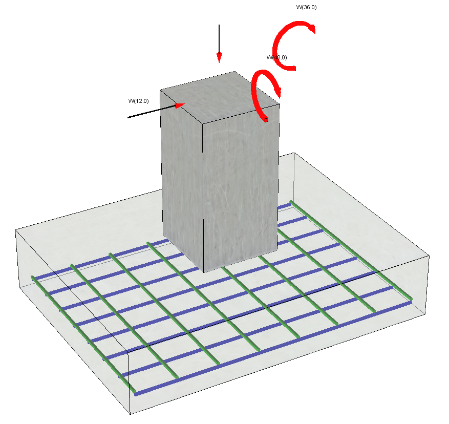
 General Footing
- Analyzes and designs individual spread footings for uniaxial or true biaxial moment
- Incorporates user-specified factors of safety on sliding and overturning
- Offers ability to automatically increase allowable soil bearing pressure as a user-specified function of footing width and/or depth below a reference elevation
- Permits the application of vertical loads, overburden loads, shears, and moments
- Allows the definition of eccentricity for vertical loads
- Provides option to automatically calculate footing plan dimensions and thickness
- Offers option to enter user-specified allowable stress increase factor for soil bearing pressure
- User defined reinforcing
- Offers the convenience of fill-in-the-blanks style forms and instantaneous recalculation to facilitate the evaluation of "what-if" scenarios
- Provides highly efficient results summaries as well as generous detail in the on-screen and printed results
- Includes rich, 3D graphics that support zoom, pan, and many customizable view options. Example 3D image shown below.
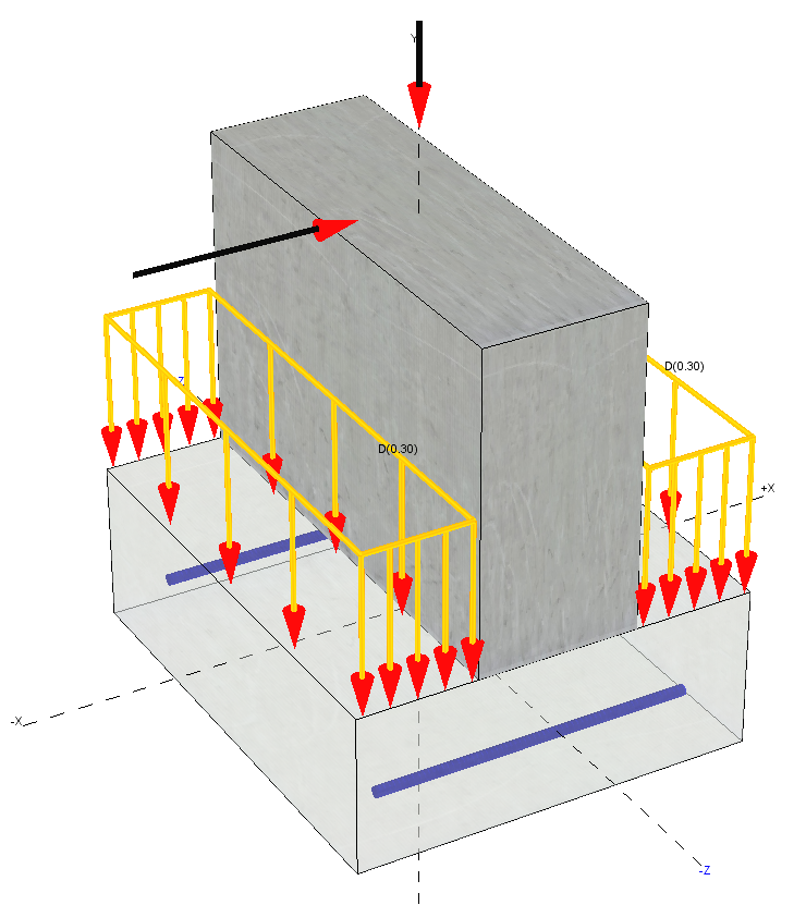
 Wall Footing
- Analyzes and designs individual wall footings
- Incorporates user-specified factors of safety on sliding and overturning
- Offers ability to automatically increase allowable soil bearing pressure as a user-specified function of footing width and/or depth below a reference elevation
- Permits the application of vertical loads, overburden loads, shears, and moments
- Provides option to automatically calculate footing width and thickness
- Offers option to enter user-specified allowable stress increase factor for soil bearing pressure
- User defined reinforcing
- Offers the convenience of fill-in-the-blanks style forms and instantaneous recalculation to facilitate the evaluation of "what-if" scenarios
- Provides highly efficient results summaries as well as generous detail in the on-screen and printed results
- Includes rich, 3D graphics that support zoom, pan, and many customizable view options. Example 3D image shown below.
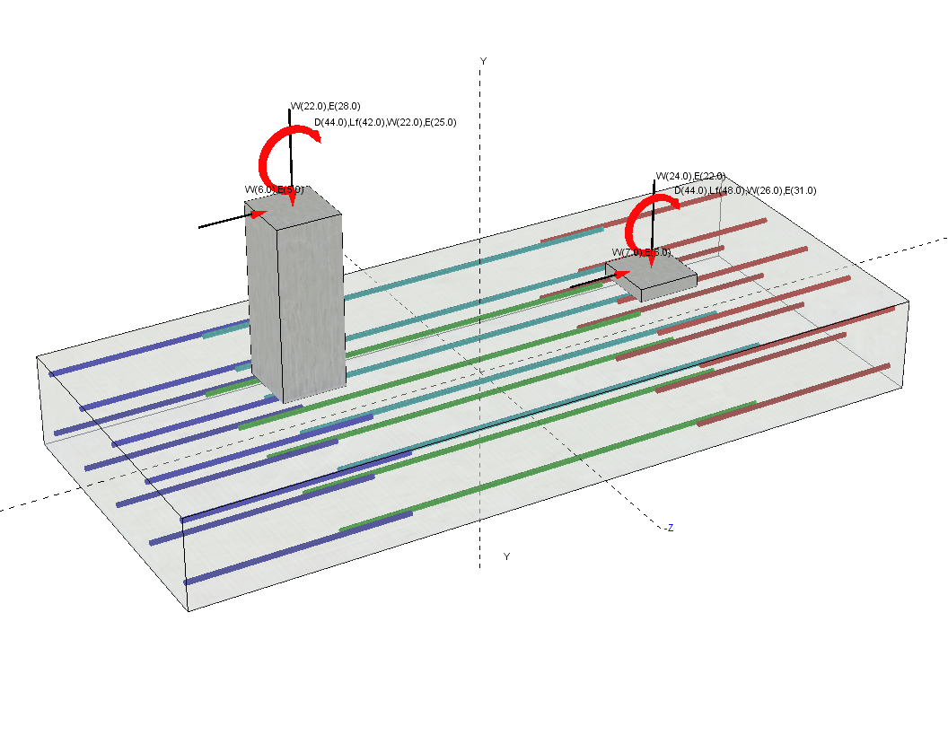
 Combined Footing
- Analyzes and designs combined footings subject to loads from two columns
- Incorporates user-specified factors of safety on sliding and overturning
- Offers ability to automatically increase allowable soil bearing pressure as a user-specified function of footing width and/or depth below a reference elevation
- Permits the application of vertical loads, overburden loads, shears, and moments
- Offers option to enter user-specified allowable stress increase factor for soil bearing pressure
- User defined reinforcing
- Offers the convenience of fill-in-the-blanks style forms and instantaneous recalculation to facilitate the evaluation of "what-if" scenarios
- Provides highly efficient results summaries as well as generous detail in the on-screen and printed results
- Includes rich, 3D graphics that support zoom, pan, and many customizable view options. Example 3D image shown below.
 Point Load on Slab
- Evaluates an unreinforced, soil-supported slab subject to rectangular patch loads
- Incorporates user-specified factor of safety
- Permits the application of vertical loads
- Incorporates either ASD or LRFD design methodology
- Offers the convenience of fill-in-the-blanks style forms and instantaneous recalculation to facilitate the evaluation of "what-if" scenarios
- Provides highly efficient results summaries as well as generous detail in the on-screen and printed results
 2-D Frame Analysis
- Provides general purpose 2D frame analysis capability
- Incorporates stress checking based on ASD or LRFD design methodology
- Frame Wizard offers the ability to quickly define geometry parametrically for many typical configurations of trusses and frames
- Features free-form definition of joint coordinates and member incidences
- Joint generation function facilitates the automatic generation of joints and members for repetitive geometry
- Allows loads to be applied to joints and to members
- Offers option of fixed or free boundary conditions
- Includes full wood and rolled steel section databases
- Offers the convenience of fill-in-the-blanks style forms and instantaneous recalculation to facilitate the evaluation of "what-if" scenarios
- Provides highly efficient results summaries as well as generous detail in the on-screen and printed results
 Torsional Analysis of Rigid Diaphragms
- Analyzes a rigid diaphragm to determine the distribution of loads to resisting elements
- Incorporates user-specified diaphragm force and two options for specifying optional orthogonal force
- Considers user-specified point of application of diaphragm force
- Automatically incorporates accidental torsion due to minimum eccentricity as required by ASCE 7
- Creates a load application point at a user-specified number of locations around an ellipse defined by the eccentricities along the two axes of the diaphragm
- Applies the vector sum of the primary and orthogonal force components in a user-specified number of directions at each load application point, or varies the load in an elliptical pattern between two specified magnitudes that occur at 90 degrees to each other
- Convenient input tools facilitate the data entry for up to 160 resisting elements of walls, beams, or general resisting elements of specified stiffness
- Offers the convenience of fill-in-the-blanks style forms and instantaneous recalculation to facilitate the evaluation of "what-if" scenarios
- Provides highly efficient results summaries as well as generous detail in the on-screen and printed results
 General Section Property Calculator
- Analyzes a user-defined section and reports section properties
- Includes full rolled steel section database
- Permits rectangular and circular shapes to be defined and incorporated into the section
- Includes eight parametrically defined custom shapes
- Sketches the section and reports area, moments of inertia, radii of gyration, elastic and plastic section moduli, c.g. locations, and dimensions from c.g. to extreme edges
- Offers the convenience of fill-in-the-blanks style forms and instantaneous recalculation to facilitate the evaluation of "what-if" scenarios
- Provides highly efficient results summaries as well as generous detail in the on-screen and printed results
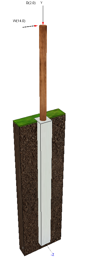
 Pole Footing Embedded in Soil
- Analyzes a pole footing embedded in soil and returns the minimum required embedment depth or the resulting pressures based on a user-specified embedment depth
- Evaluates round or square poles
- Provides option to consider restraint at ground surface
- Offers two options to limit the maximum allowable lateral bearing pressure
- Permits the application of lateral concentrated loads, lateral distributed loads, applied moments, and vertical loads
- Offers the convenience of fill-in-the-blanks style forms and instantaneous recalculation to facilitate the evaluation of "what-if" scenarios
- Provides highly efficient results summaries as well as generous detail in the on-screen and printed results
- Includes rich, 3D graphics that support zoom, pan, and many customizable view options. Example 3D image shown below.
 Pile Group Analysis
- Analyzes a pile group for the applied loads and returns the maximum and minimum pile forces
- Accommodates pile groups with up to twelve piles
- All pile locations are user-defined, making it possible to evaluate pile groups in their as-driven locations
- Allows vertical loads to be applied at up to three different locations on a pile cap
- Force distribution is based on the assumptions that the pile cap is rigid and that all piles have equal vertical stiffness
- Offers the convenience of fill-in-the-blanks style forms and instantaneous recalculation to facilitate the evaluation of "what-if" scenarios
- Provides highly efficient results summaries as well as generous detail in the on-screen and printed results
 Rebar Development
- Calculates straight development length, hooked development length, and lap splice lengths
- Allows up to 15 individually identifiable development/splice conditions to be defined per calculation item
- Performs calculations according to ACI 318-14/11/08/05
- Convenient dropdown list boxes and simple checkboxes collect all of the pertinent data required
- Reports straight and hooked development lengths for bars in tension and in compression
- Reports splice lengths for Class A, Class B, and compression splices
- Offers the convenience of fill-in-the-blanks style forms and instantaneous recalculation to facilitate the evaluation of "what-if" scenarios
- Provides highly efficient summaries and generous detail in the on-screen and printed results
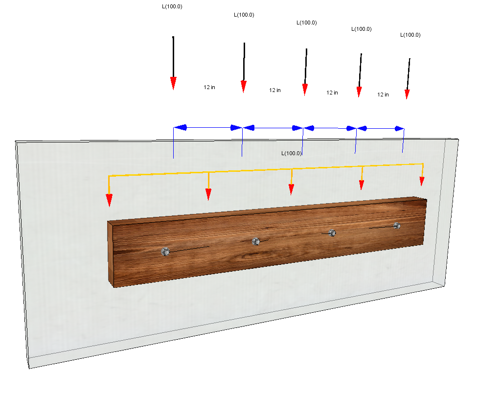
 Wood Ledger
- Analyzes and designs a wood ledger connected to a wood or concrete support with steel bolts at a user-defined spacing
- Includes full wood stress database
- Permits loads to be applied as uniformly distributed vertical loads, repetitive concentrated vertical loads at a uniform spacing, and horizontally oriented shear loads
- Offers the convenience of fill-in-the-blanks style forms and instantaneous recalculation to facilitate the evaluation of "what-if" scenarios
- Provides highly efficient results summaries as well as generous detail in the on-screen and printed results
- Includes rich, 3D graphics that support zoom, pan, and many customizable view options. Example 3D image shown below.
 Steel Base Plate
- Analyzes and designs individual steel base plates
- Includes full rolled steel section database for column selection
- Incorporates axial loads, shear loads parallel to the web of a wide flange column, and moments about the strong axis of the column
- Offers two options for determining the assumed bearing area
- Incorporates either ASD or LRFD design methodology
- Provides flexible method of defining anchor bolt locations and strengths
- Offers the convenience of fill-in-the-blanks style forms and instantaneous recalculation to facilitate the evaluation of "what-if" scenarios
- Provides highly efficient results summaries as well as generous detail in the on-screen and printed results
 Steel Bolt Group Analysis
- Analyzes a user-defined pattern of bolts and returns the total shear force applied to each bolt in the group
- Allows complete flexibility with regard to the location of the center of force and the orientation of the force
- Incorporates either ASD or LRFD design methodology
- Offers the convenience of fill-in-the-blanks style forms and instantaneous recalculation to facilitate the evaluation of "what-if" scenarios
- Provides highly efficient results summaries as well as generous detail in the on-screen and printed results
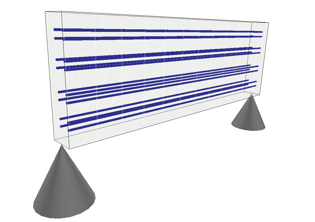
 Beam on Elastic Foundation
- Analyzes and designs individual soil-supported reinforced concrete beams
- Permits up to six groups of reinforcing bars per span
- Capable of analyzing and designing rectangular, tee, H, and trapezoidal shaped sections
- Incorporates point loads, concentrated moments, full and partial-length uniform loads, and trapezoidal loads
- Considers user-specified allowable soil bearing pressure
- Offers the convenience of fill-in-the-blanks style forms and instantaneous recalculation to facilitate the evaluation of "what-if" scenarios
- Provides highly efficient results summaries as well as generous detail in the on-screen and printed results
- Provides sketch graphics to verify dimensions and load placement - including rich, 3D graphics that support zoom, pan, and many customizable view options. Example 3D image shown below.
- Provides shear, moment and deflection diagrams for all load cases